It's probaly a bit early to be thinking about wiring looms and brake lines when there is still so much to do on suspension and engine, but it seemed to make sense to tackle these jobs whilst the chassis is on the rotisserie making access to the underside so much easier
A new RHD wiring loom was included in the job lot of parts I purchased at the start of the project, although this was for a BJ8 and not for my BJ7. How different could it be? Once I started to go through it, the answer is quite a lot. One of the main upgrades on the BJ8 was a totally redesigned dashboard but with basically the same functionality. Most noticably most of the switches are moved to a new console in the centre of the dash - these would have to be re-routed to their original BJ7 positions on the dash. The speedo, tacho and fuel gauge are in the same relative position but the dual gauge is moved to other side of the steering wheel. The BJ7 tacho is a mechanical one whereas the BJ8 is an electronic version so this required modication too.
Checking over the original switches and instruments, apart from being a bit grubby, they all appeared to still be functional so can be re-used. Difference being BJ7 switches have screw terminals whereas BJ8 have mainly Lucar connectors - more on that later.
Alternator
As was common with all BMC vehicles of the time, the Healey gained its electrical power from a dynamo (generator) that requires a stabilizer (control box) to smooth the output. Alternators are more efficient and do a better job at providing electricity to the battery. Alternators turn at higher speed, improving output when the engine is idling - a generator would discharge at idle instead of charging. The ac voltage is smoothed by built-in diodes thus negating the need for the Control Box, but are only available in -ve earth so I will I change the polarity of the vehicle - for now this just means the terminals and main cable from the battery to the solenoid is red. The original control box is now redundant so I purchased a slightly newer replacement (keeping the original in case anyone wants to revert back) that utilizes spade terminal instead of screw terminal - making it more compatible with the BJ8 loom. The relay gubbins were stripped out and A, A1 & F terminals electrically joined together so that the unit now becomes a terminal box which does not look out of place in the engine bay. As the output from the alternator is greater than the dynamo and additional 35A cable was routed in parallel from the alternator back to the solenoid.
Doing this upgrade on the MGA was simple process just swapping the bracket for a Mini bracket. Not so simple on the Healey as the bracket is affixed to the tappet cover. A clever solution will have to be sort later.
Electronic Ignition
An often source of frustration when starting the engine is the distributor points. Technology has caught up and electronic ignition is common place these days. Accuspark (other makes are available) produce a simple replacement to the points that fits inside the original Lucas 25D distributor so, apart from an extra earth wire, you would not notice this change. Again, another reason to change polarity to -ve earth. The wiring to the distributor had to be changed anyway as the BJ8 has an electronic tach running off the distributor wire so that had to be removed as the BJ7 is mechanical.
Dip Switch
I'd never really liked the idea of a foot operated switch to dip the headlights since the days of driving my mother's Mini many years ago and was a refinement I made to the MGA. Instead of the foot switch, the light switch is wired to a relay from a VW Beetle or T2 Bay Camper (part number 111-941-583) and controlled by a long levered momentary flick switch now mounted on the dash to the left of the steering wheel. With the lights on, each flick of the switch will toggle between Dip and Main Beam. With the light switch turned off, the flick switch will flash the dipped headlights - another benefit of this system.
Indicators
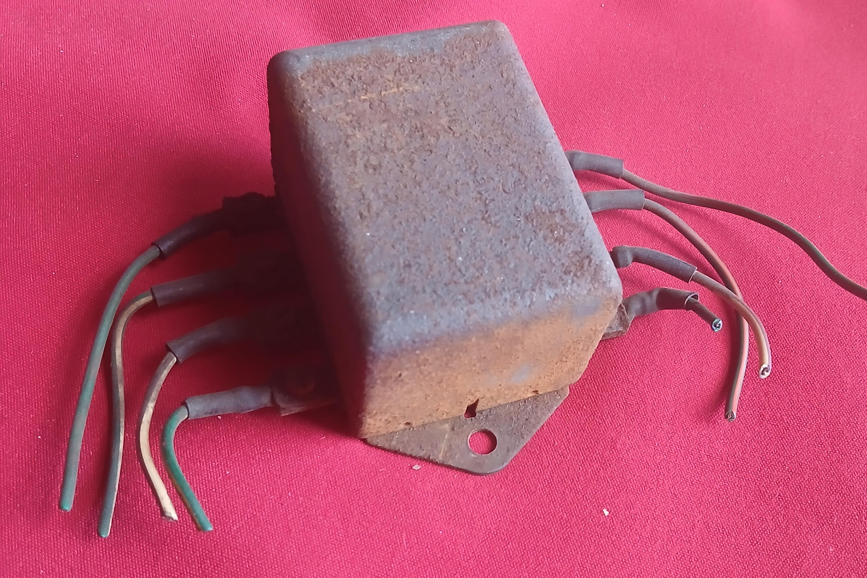
In the mid 1950s, indicators were a new thing - hand signals were the order of the day (I remember being tested on hand signals when learning to drive). When they became compulsory for the US market, Lucas produced a nifty relay box (DB10) to use the red brake lights as indicators, avoiding the need for BMC to redsign the wiring loom - amber indicators were later added to the late BJ8s. Hazard Warning Lights (or Four-Way Flashers) were not thought of for another couple of decades. Adding a Hazard Warning Lights would be simple in a newer vehicle, but not so straight forward with this Lucas DB10 relay box. Several solutions are out there, but I wanted to incorporate a solution that would be able to use without the ignition being on, but solutions that allow this tend to have a hot feed to the flasher meaning the ignition switch would be bypassed if hazards are on and turn signal is applied - not only a security failure but channels the ignition current along the lightng circuit. Added to this the original DB10 was pretty well rusted up and the internal relays were seized.
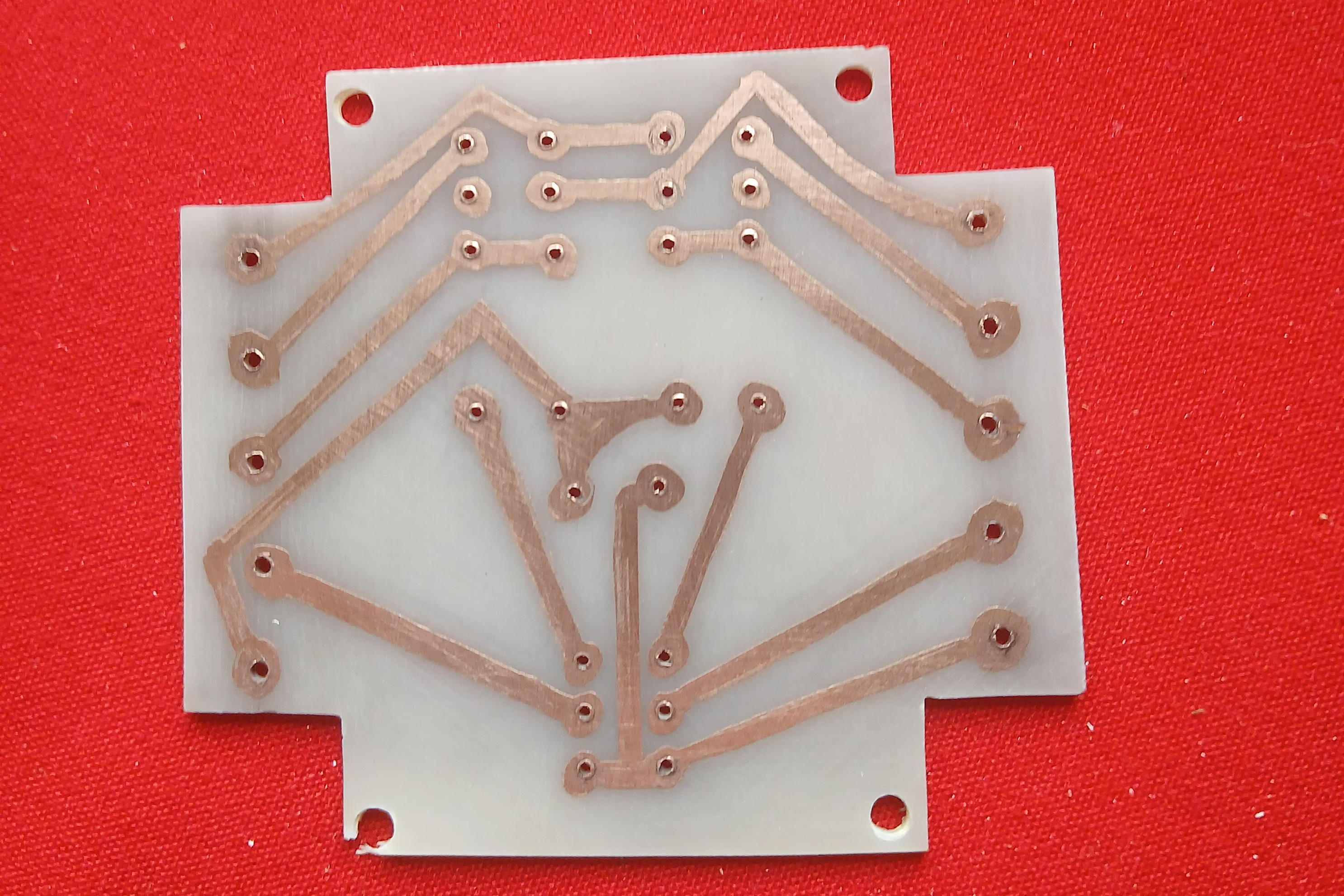
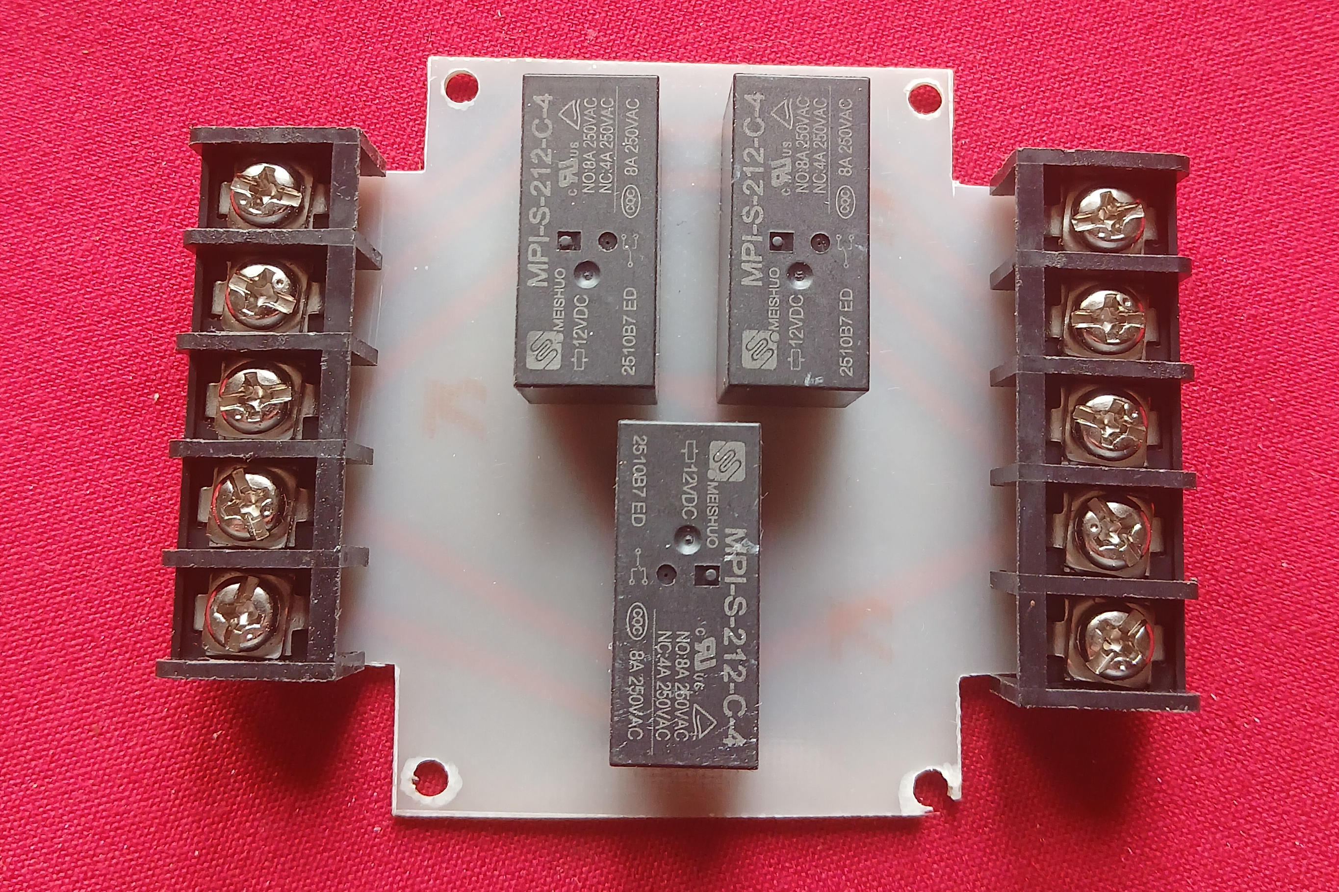
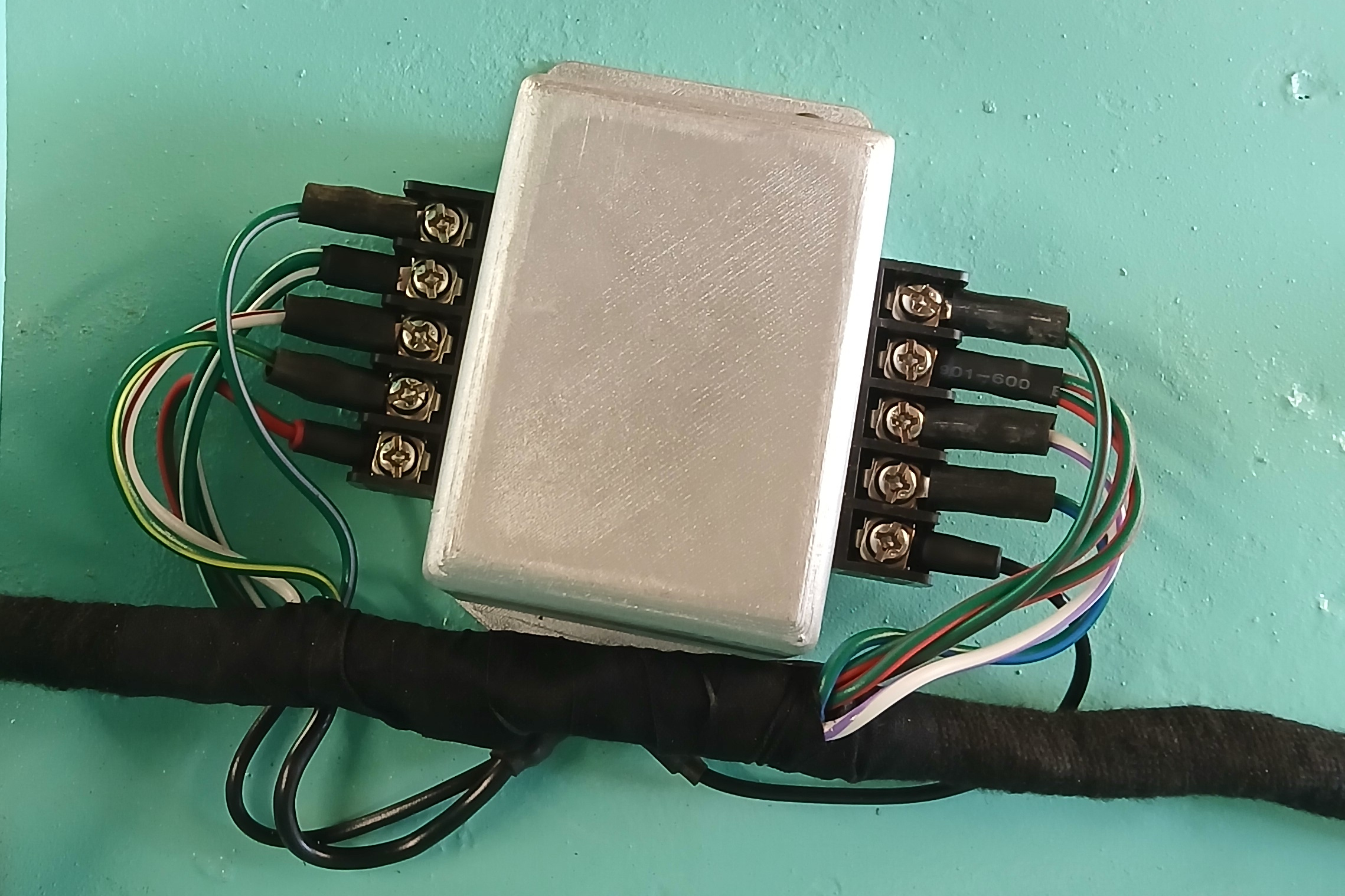
My solution was to layout a new PCB incorporating three DPDT relays with the same footprint as the DB10 but with two extra inputs - a switched 12v and feed from the hazard switch. Intitially I'd intended utilising the original DB10 case but that was so rusted it would never look the part. Instead I 3D printed a new case to the same dimensions as the old and sprayed in silver paint to at least give the correct look.
Click thumbnail
The BJ7 dash has a single indicator light in the centre of the dash instruments whereas the BJ8 has separate lights for left and right indicators. To BJ7ize the wiring loom would require further modification but I used this to my advantage by keeping the dual warning light system (adding two lights to the dash) which freed up the original lamp position for the hazard switch.
A couple more relays were needed to provide 12v to the new DB10 when the hazards are switched without the ignition on, and also to allow the indicator dash lamps to flash when hazards are on. Again, a relay cradle was 3D printed to carry these relays together with the Dip Switch relay that would be affixed to the bulkhead behind the dash.
Windsreen Washer / Wiper
Another lesson learnt from the MGA project was the windscreen washer / wipers. The original washers had a water bottle inaccessibly located under the dash on the parcel shelf and a manual push pump on the passenger side of the dash - again, not to my taste. My original BJ7 had an aftermarket cigar lighter in the centre of the dash, and the new RHD dash already had the large hole for the washer pump on the passenger side. I wanted to the keep the cigar lighter as a feature, not that I would be smoking cigars, but for use as a power output for phone charging and Sat Nav. The washer bottle (now easily located in the engine bay) would be run from an electric water pump behind the dash and the original wiper switch changed for a dual wiper / washer switch with first position for wiper and momentary second position for the washers.
The wipers needed a general overhaul. The motor was working after all the old grease had been dug out and replaced with new. One of the wheel boxes was seized so that was replaced with a used part. The rubbers had gone hard so new ones inserted prior to fitting.
Fuse Box
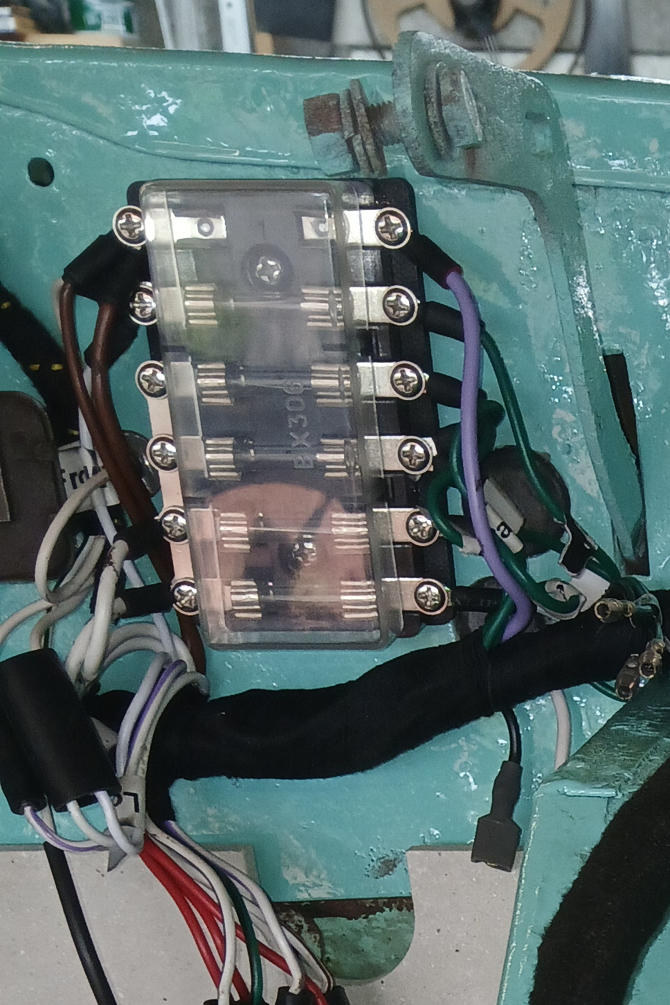 The original two fuse fuse box was in a pretty poor state so needed replacing. Instead of replacing with like for like I opted for a slightly more moddern six fuse version and separated out the wires to individual circuits to give better protection. 3D printer came into its own again to make a backing to affix the fuse box whilst utilizing the original fixing holes - just in case anyone wants the original back.
Brake Switch
The brake lines had to be reconfigured to facilitate changing to RHD. Whilst doing so I took the opportuity of adding a servo - it would have been an option at the time of manufacture but not taken up back in 1963. The brake switch was beyond resurection which is not unusual as these switches do not have a good reputation, particularly with increased pressure from a servo. On that basis I decided not to refit an inline switch but fit a switch (Volvo part) directly onto the brake pedal. The wires in the wiring loom permitted peeling back so the original wires were connected to the switch. Hopefully, that will prevent future malfunction.
Fluid Lines & Wiring Install
The finalised wiring loom was installed in the vehicle. Brake pipes were formed from 3/16" cupro nickel pipe and routed to the four corners, with lines from resevoir to master cylinders in 1/4" pipe. The fuel line was formed from 5/16" copper pipe with end terminals soldered in place from petrol tank to pump, then pump to carbs. Finally a red 50A cable routed from rear battery compartment in the boot to the solenoid.
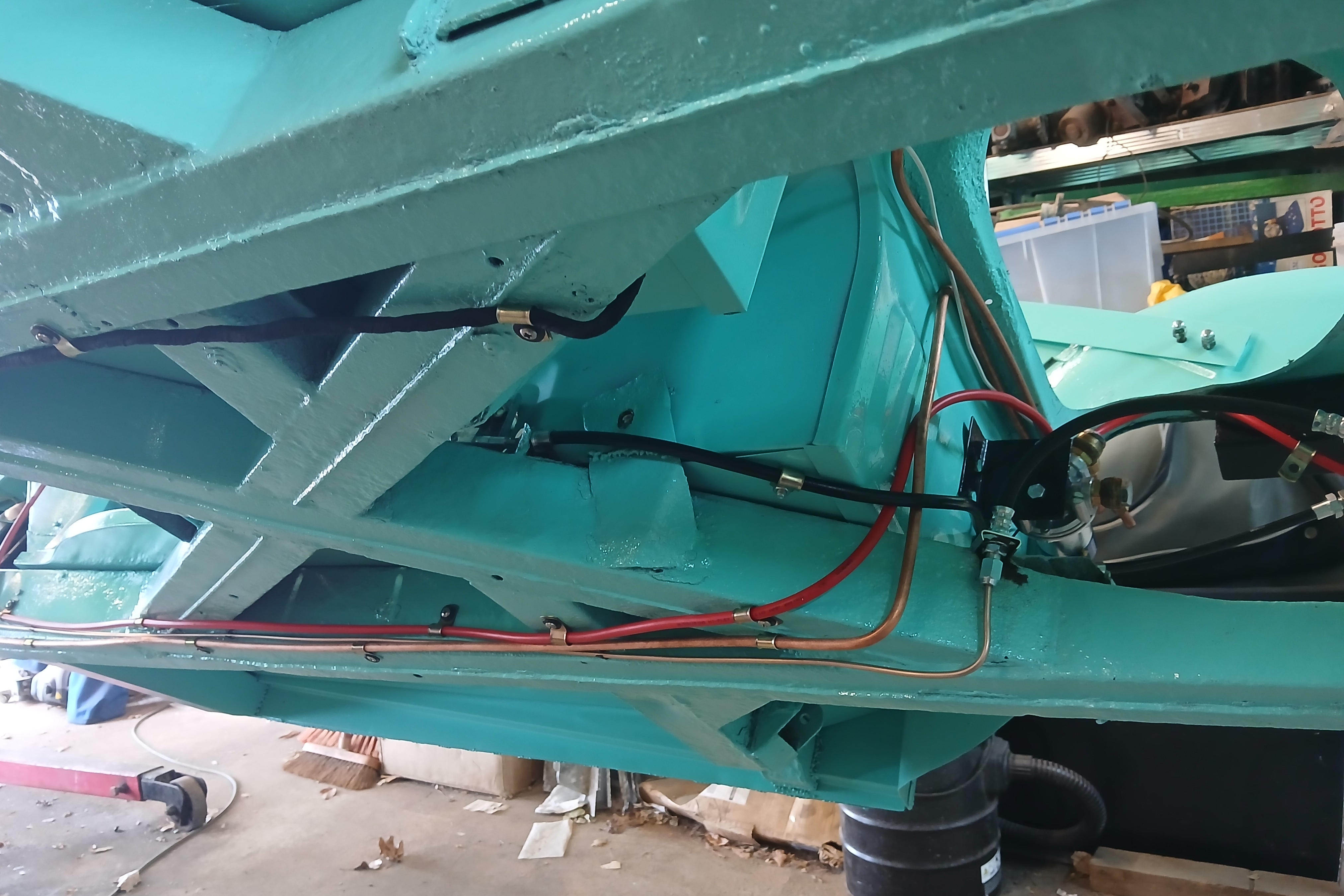
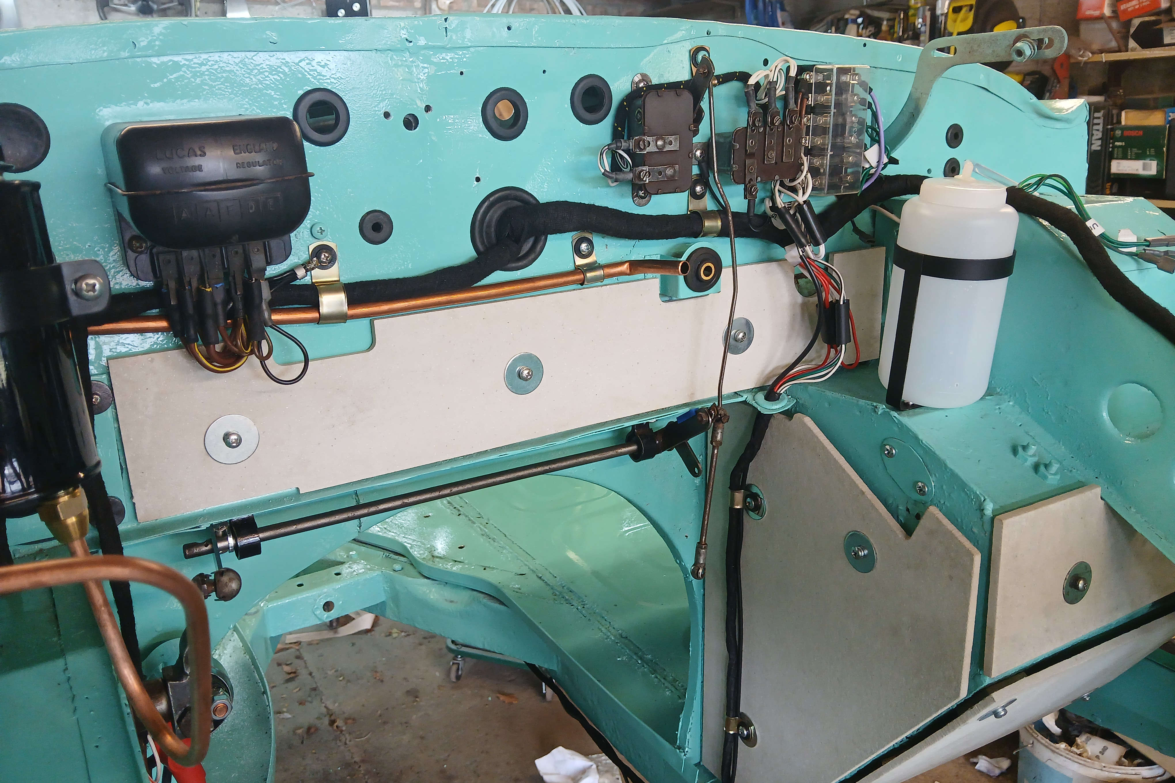
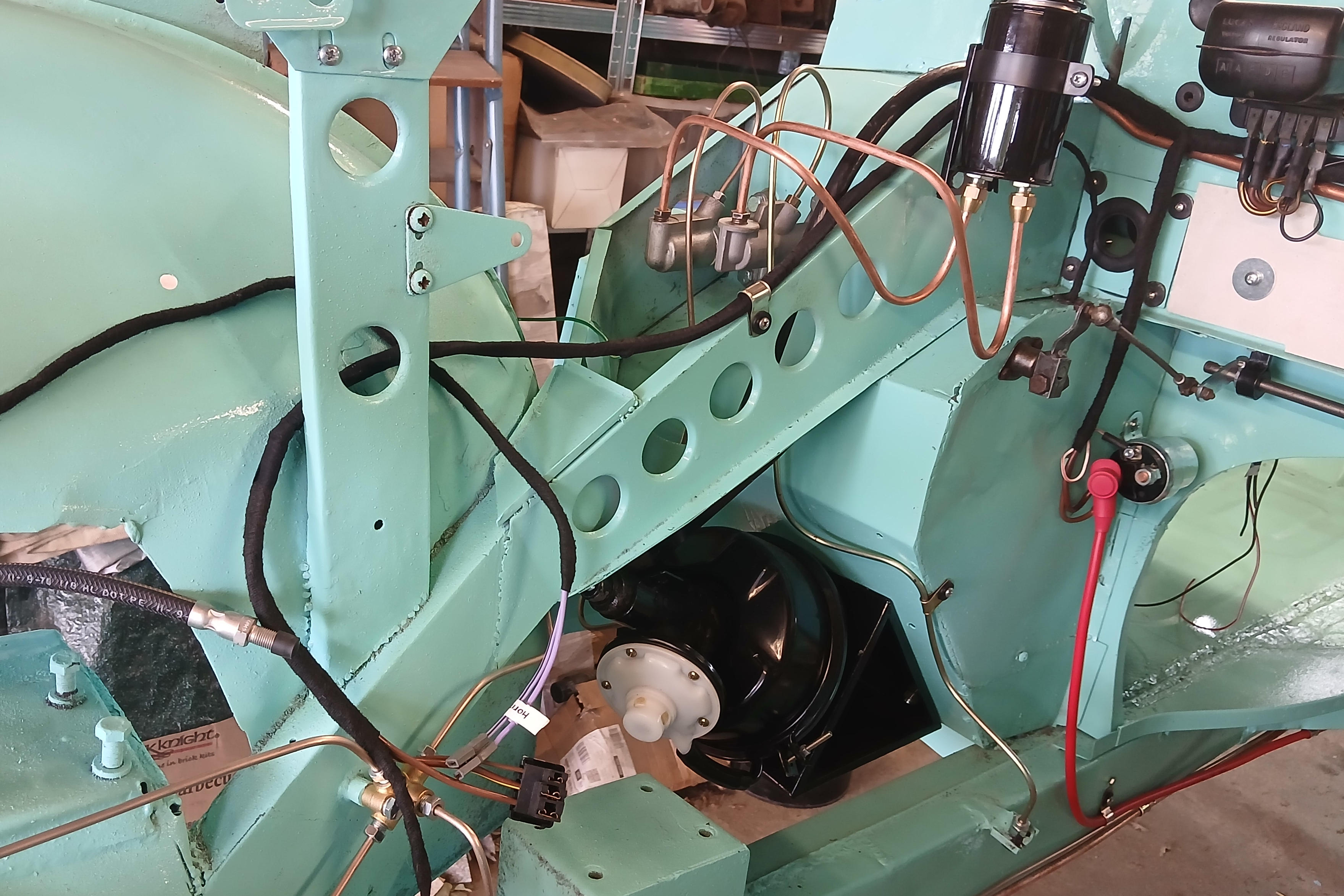
Click thumbnail