I deliberated whether to start welding some of the inner panels that would be required to get the body onto a rotisserie (viz. sills and bumper hangers), or whether to continue to strip down the major components to reduce the weight. The weight reduction won so I started to remove the engine and gearbox as a complete unit. Off came the carbs (fiddly but not corroded) and both manifolds (only two studs broken). The dynamo was removed to give a bit more room and the distributor taken out to avoid damage.
Many of the rusty bolts were putting up a fight, especially around the gearbox area. The fibreglass transmission tunnel was proving particularly difficult, not because the securing screws were ceased (they just levered out), but the hand brake lever was ceased so would not move to give room for the tunnel. Brute force won the day with a big yank on the lever to bend it out of the way - I'll have to straighten it again further down the line one day. Three of the four bolts securing the gearbox to the chassis came out relatvely easy, but the fourth was impossible - it was also impossible to get a grinder in there. I had to use my reciprocating saw to cut through the rubber mount to free it.
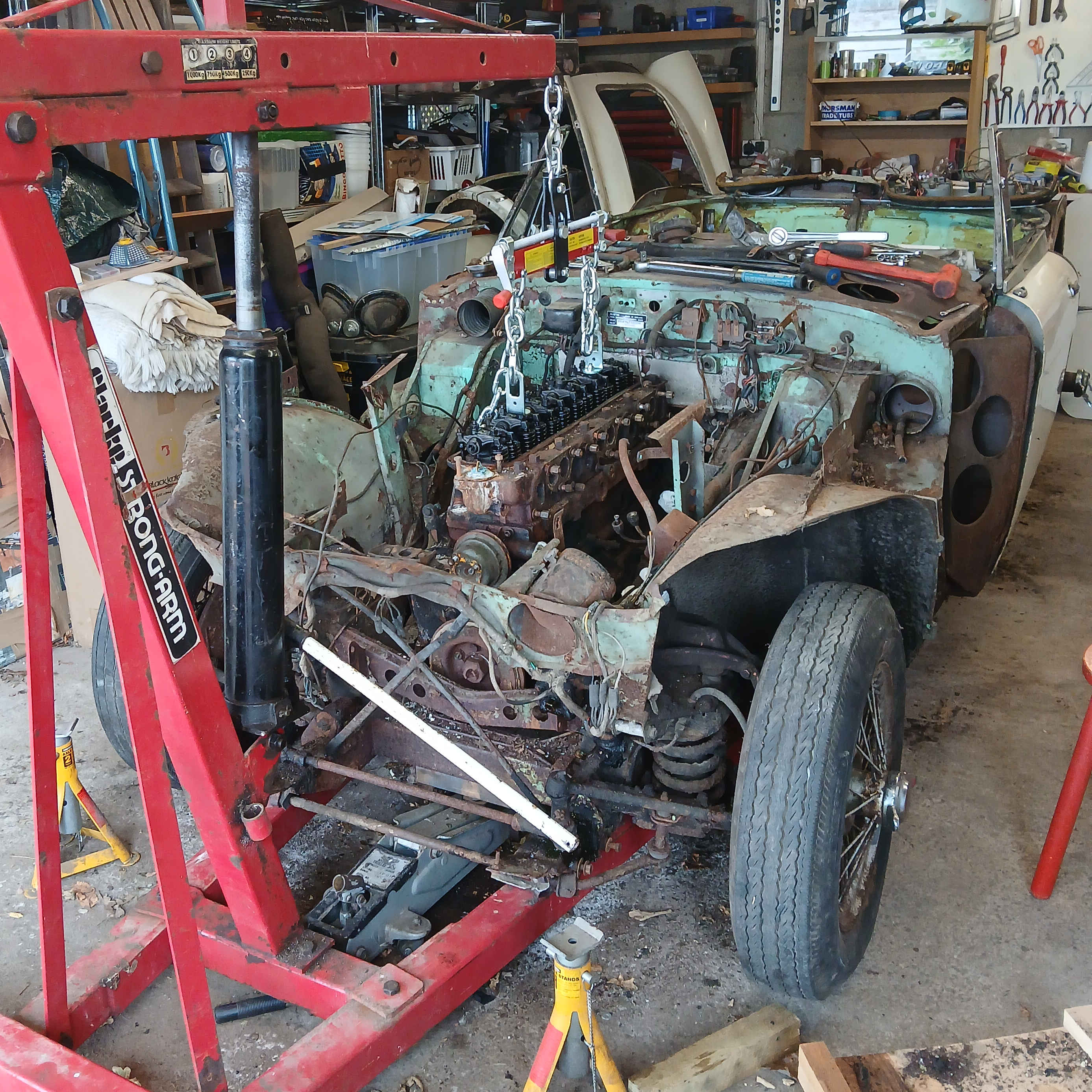
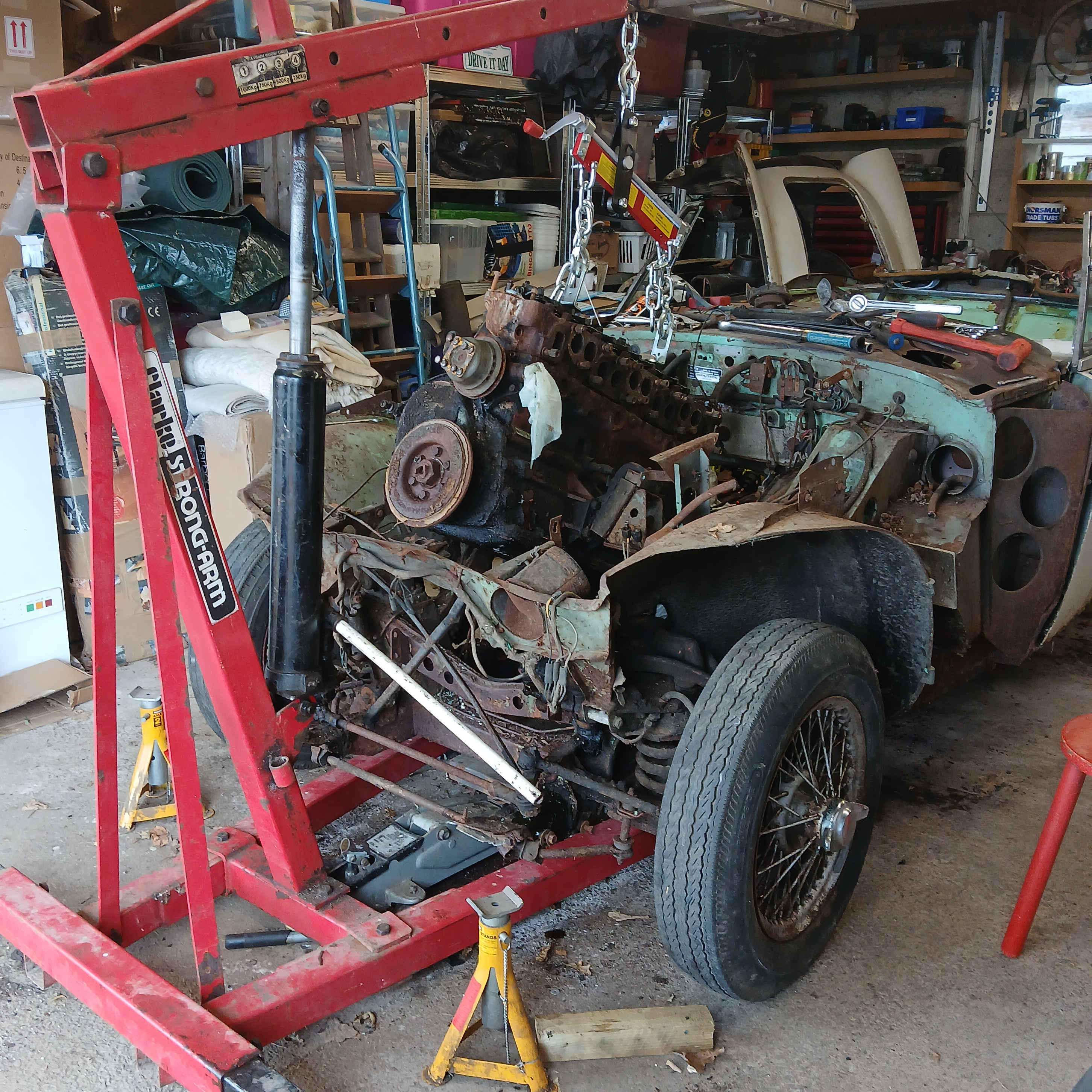
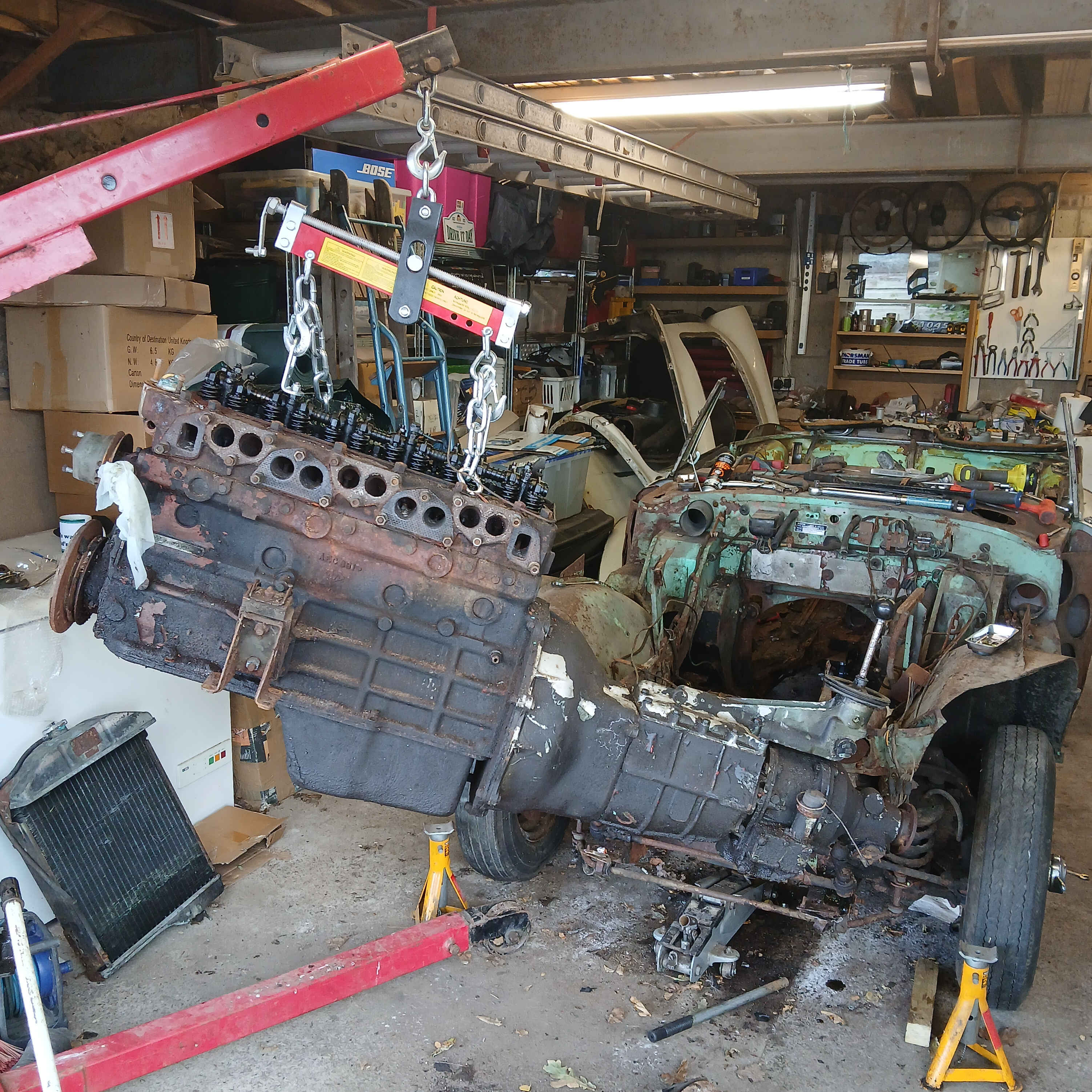
Wasting no more time I cut through the earth strap and clutch pipe instead of battling with more rusty fixings and the only thing keeping the engine in was gravity. I'd invested in a pivotting load balancer which allowed the power unit to be hoisted up at a very steep angle - a straight six engine / gearbox / overdive combination is very long needing a lot of clearance. The gear stick got caught so I temporarily removed the remote selector unit. All quite straight forward which I did on my own.
Click thumbnail
The engine will be rebuilt later but for now on to the suspension.
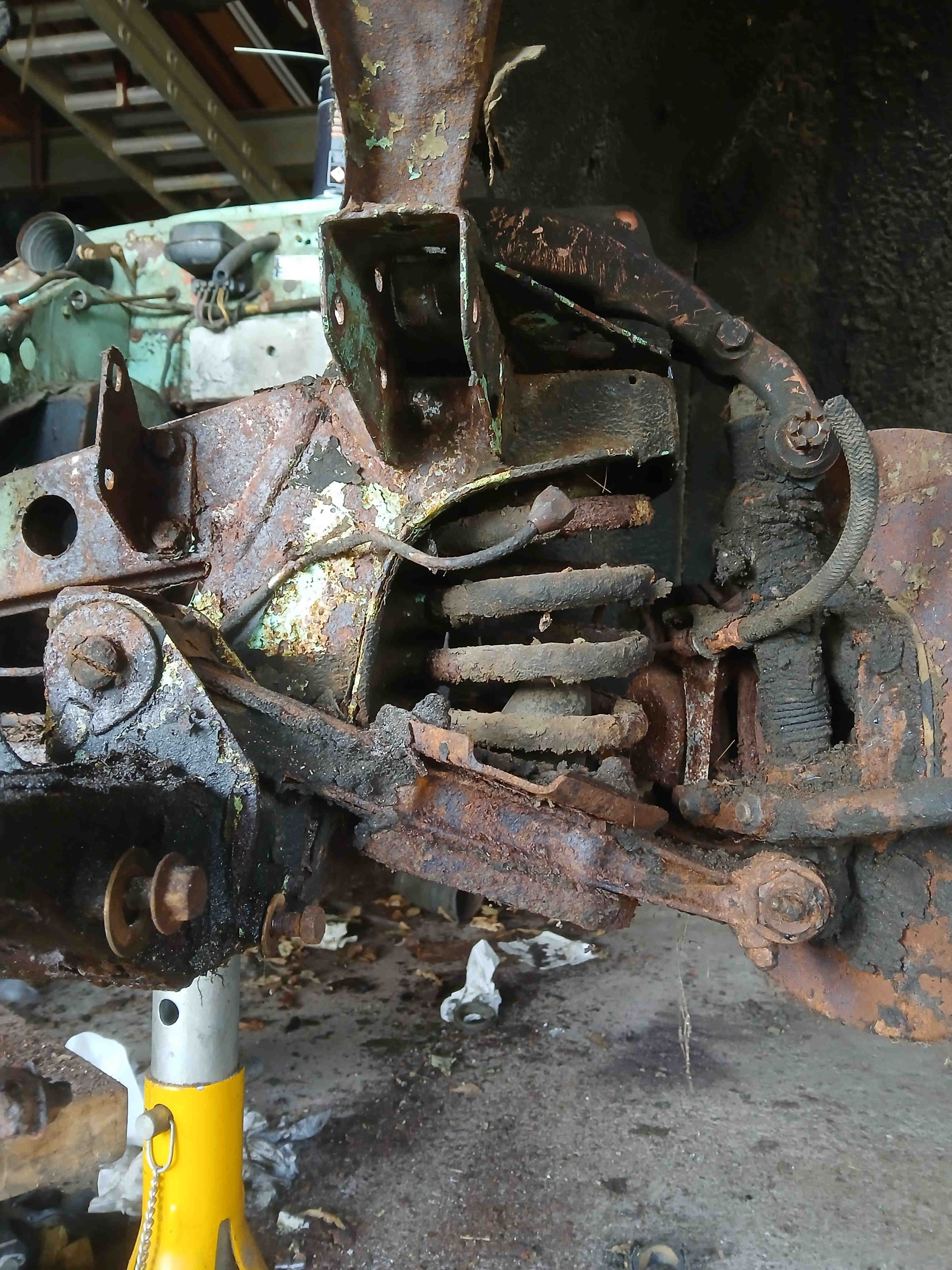
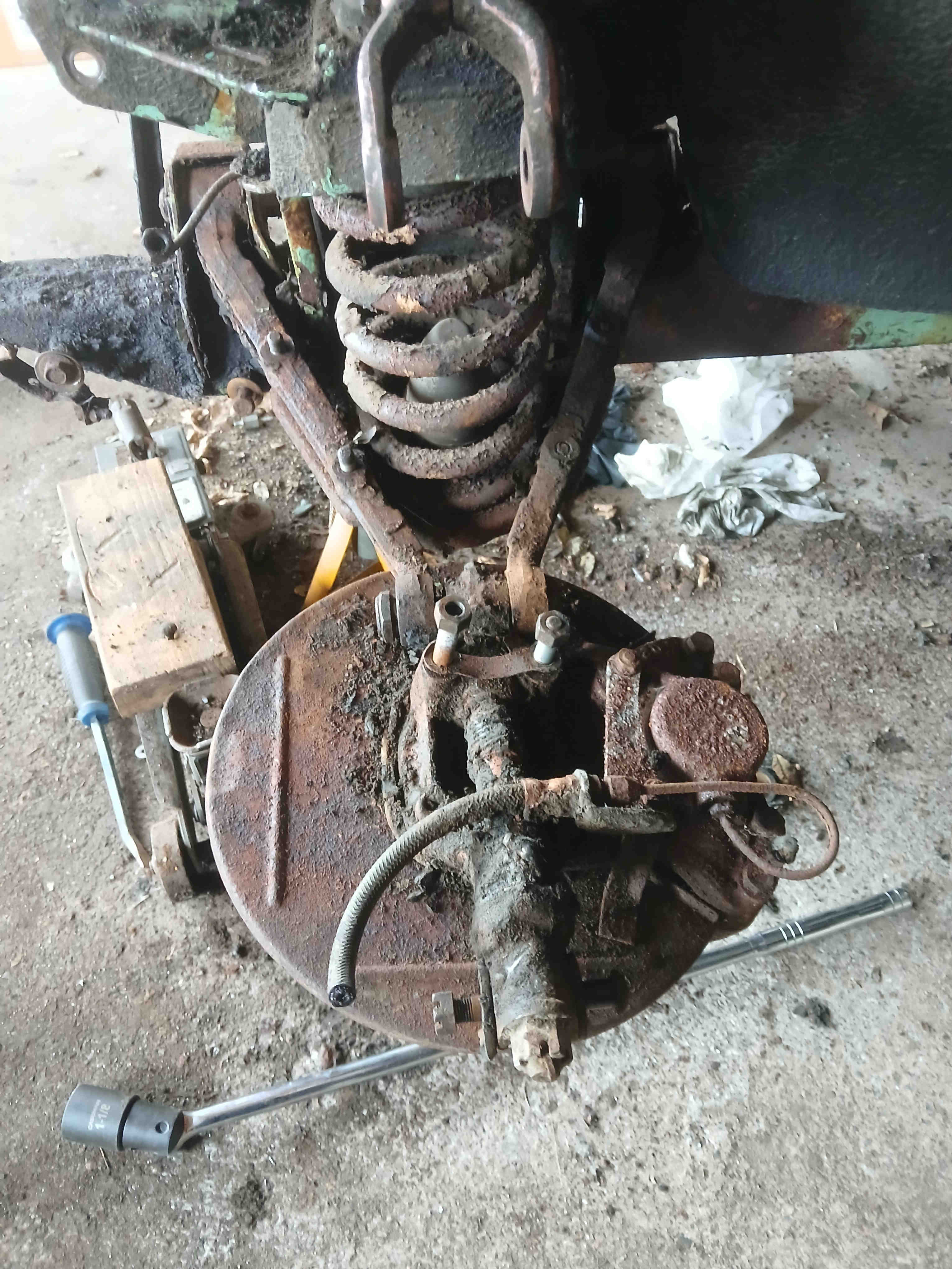
Things started quite well with the anti-roll bar coming off easily with the help of my breaker bar, as did the steering idler. The steering box, or the aluminium bracket that fixes the lower end of it, did not - steel bolts into aluminium housing like to get very friendly with each other. I ended up having to hacksaw my way through both parts to get it out. The left-hand suspension was gong well until it came to removing the wishbone arms - steel inserts in rubber bushes also like to embed them selves so these had to be hacksawed too. Same story on the right-hand side so I went straight for the hacksaw to save time. The complete suspension units will be stripped down and rebuilt prior to re-assembly.
Click thumbnail
The bolts of the rear axle undid quite easily but it was more of a challenge to pull it free of the car as it sits atop the leaf strings, so it is definately a two man job. With the help of friend Nick we were able to pull the rear axle free - it is quite a weight.
Rotisserie
Working on the inner panels is a lot easier if the whole assembly can be spin around - cuting and welding with gravity assistance is better than trying to crawl under a vehicle and perform the same function above your head. I purchase a used rotisserie from fleabay - it was originally made for a Scirocco project but, with minimal modification, should do for the Healey.
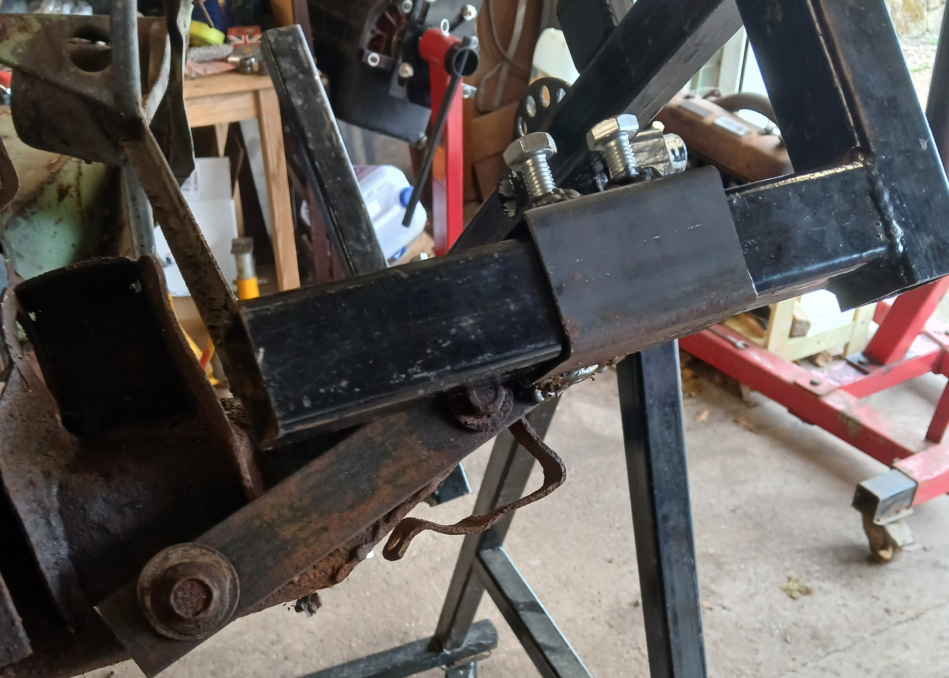
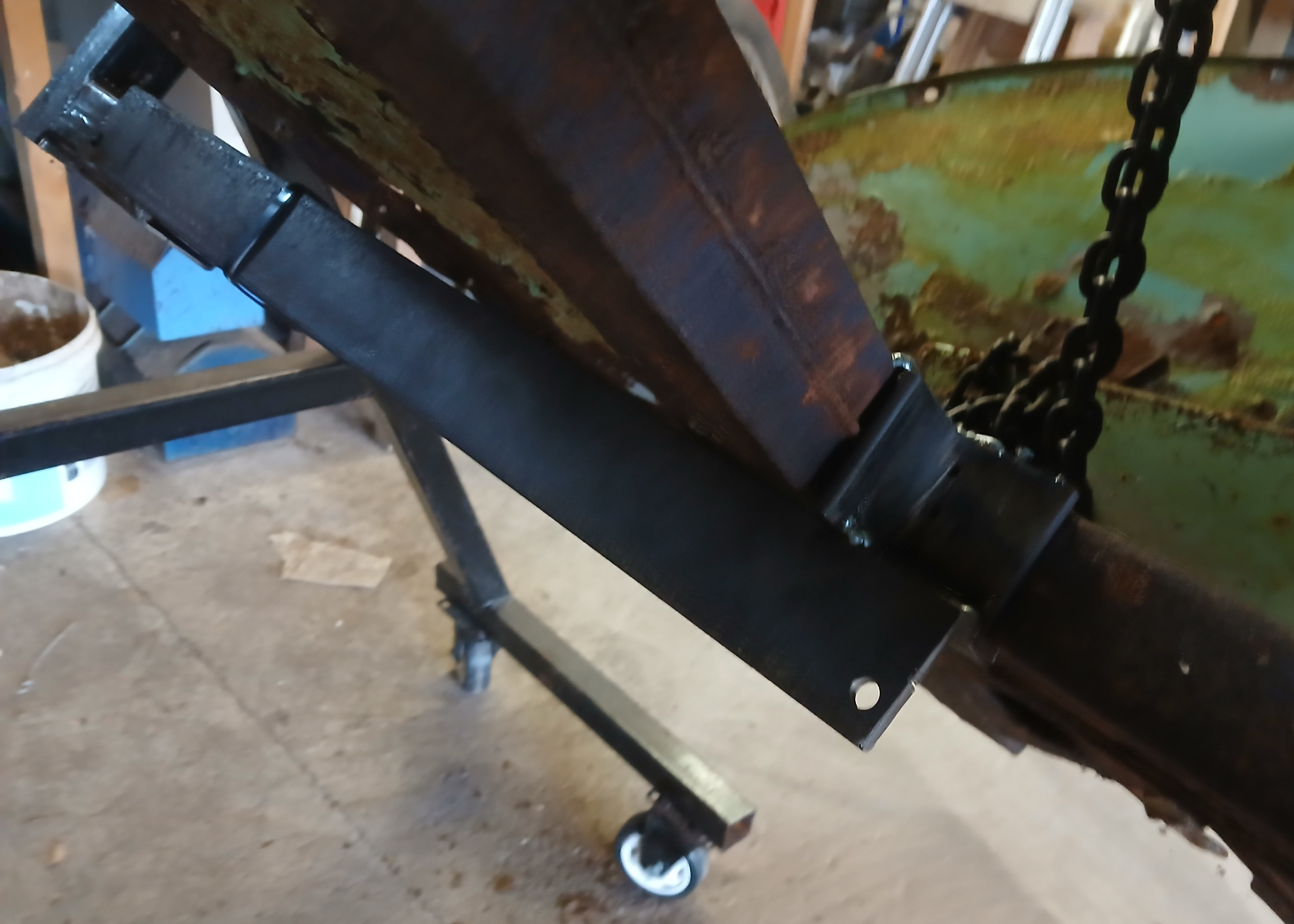
After making up brackets, the front section bolts onto the bumper mounts - so far so good. The rear section was a bit more of a challange. In theory, you could use the rear bumper mounts but (ithout the shroud in place) I did not think there would be enough lateral rigidity. Closer inspection revealed serious rust of the chassis extension and surrounding area so another solution would be required. In the end I had some substantial pieces of angle iron so welding these to the chassis where the petrol tank goes. This would be strong enough without interferring with other parts of the chassis or panels that would need to be worked on.
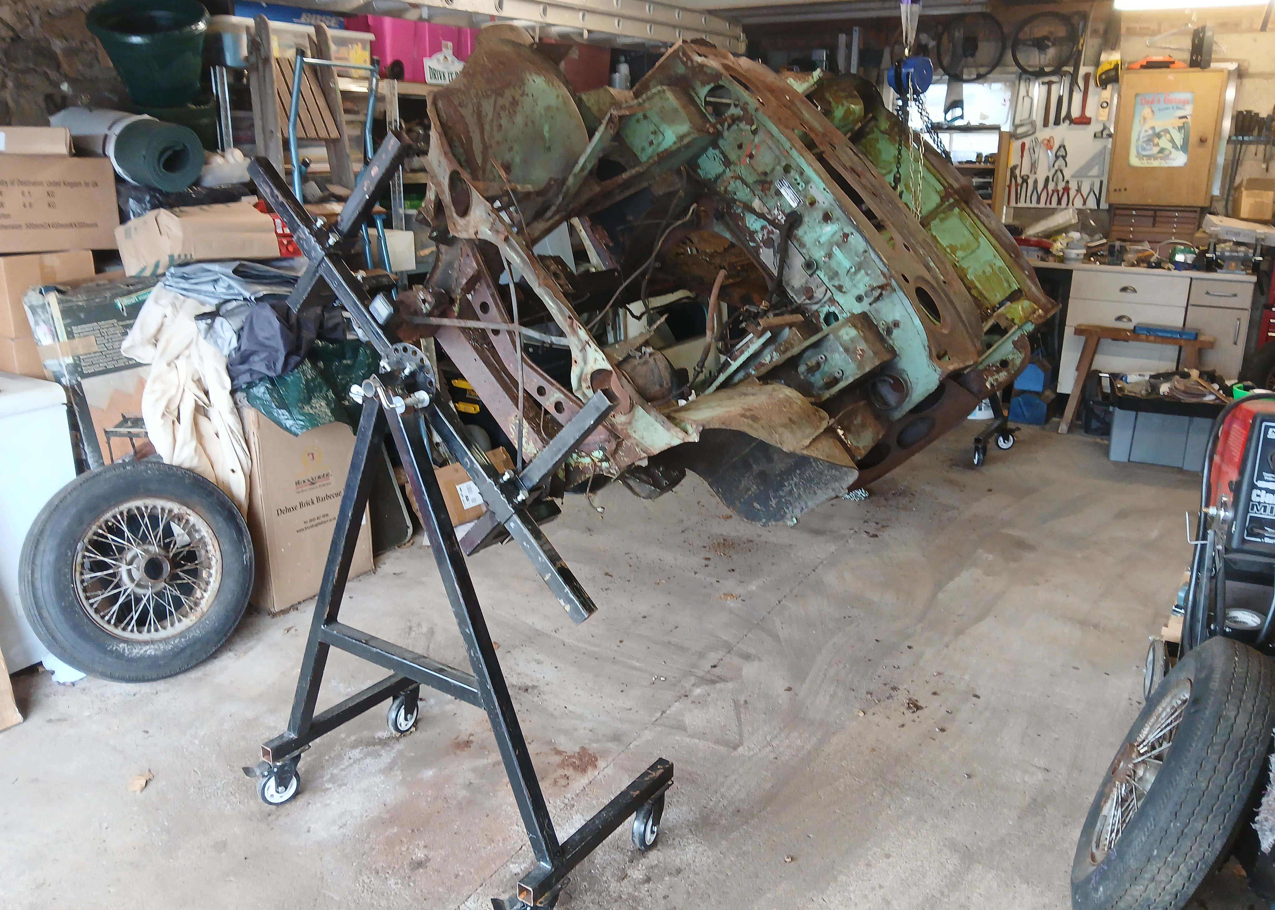
To allow the vehicle to swing 360° it needs to be high enough off the ground to pass at least 50% of the width - which is quite a lift. Also, it needs to be fairly well balanced about the centre of gravity otherwise it will just spin round to its lowest point and be difficult move to any required angle. Helpful American friends on the AHEXP.com forum came up with a figure that the centre of gravity shold be about 5½" from the top of the chassis. With the help of the engine hoist on the front and a chain pulley at the rear, I was able to lift it up onto the stands. The 5½" CoG calculation was about right meaning I am able to the whole 360° on my own.
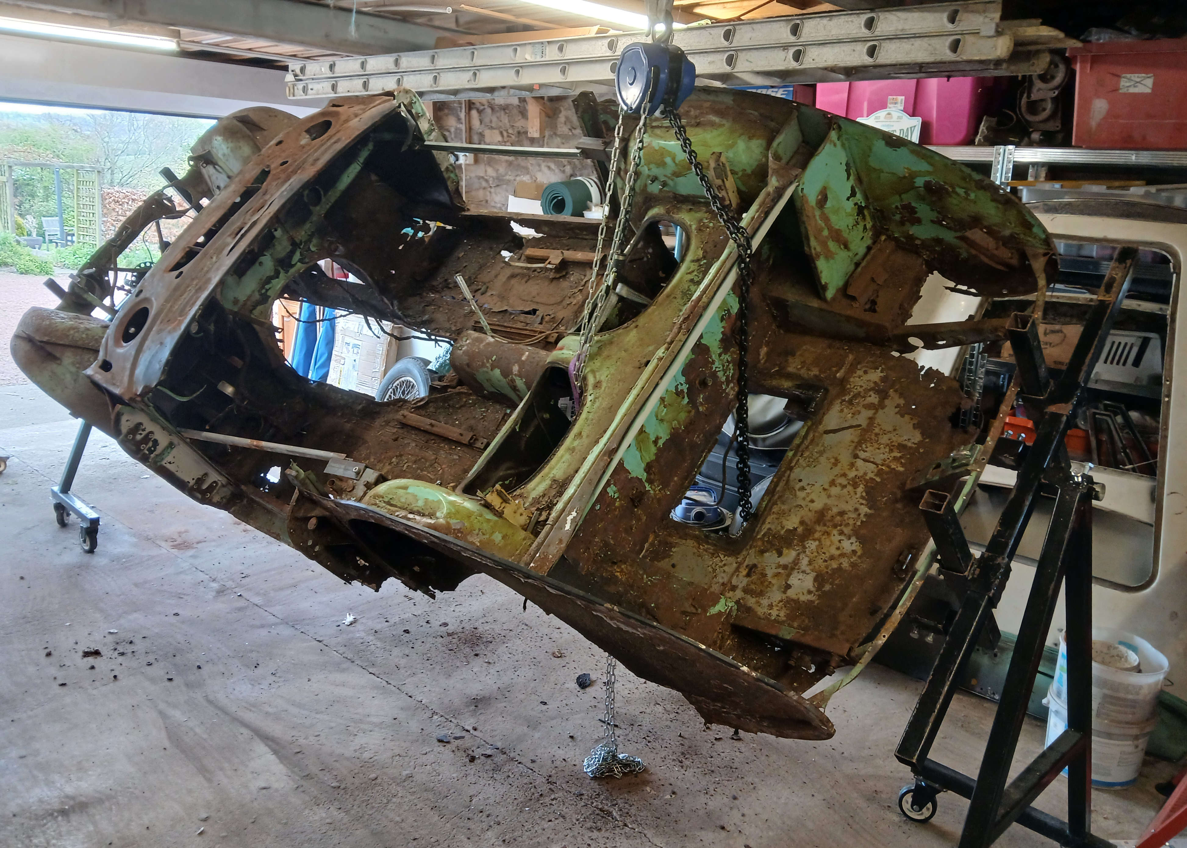
Click thumbnail
Now we can get down to some serious cutting, grinding and welding.